


GANTRY CRANE
- Single-Girder Gantry Crane
- Double Girder Gantry Crane
- Semi Gantry Crane
HOT PRODUCTS
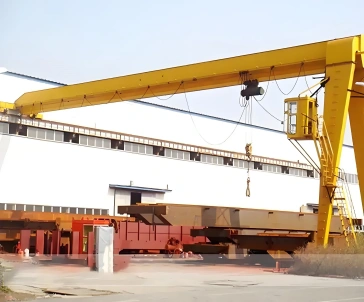
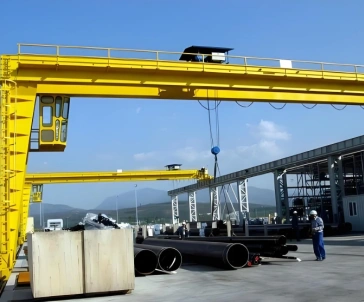
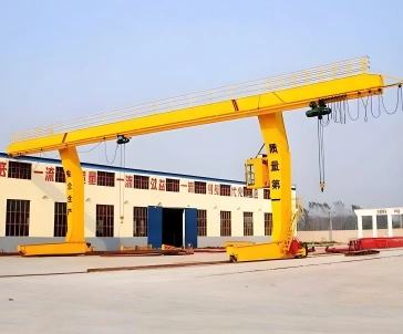
U Type Double Girder Gantry Crane


Introduction
Application Scenario
Advantages
Structural Diagram And Parameter Table
INTRODUCTION
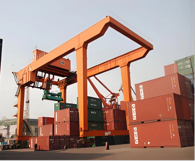
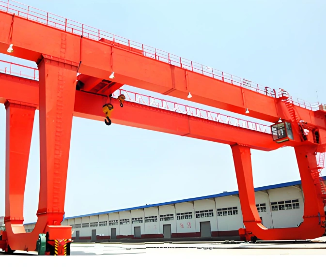
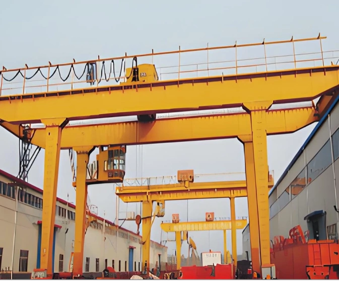
A U-Type Double Girder Gantry Crane is a heavy-duty, rail-mounted crane featuring a double-girder bridge supported by "U"-shaped legs. By omitting the lower crossbeam found in conventional A-frame gantry cranes, its unique U-shaped leg configuration maximizes clearance, allowing bulky, long, or wide materials to pass smoothly between the legs without obstruction.
APPLICATION SCENARIO
Container Freight Stations & Inland Waterway Ports: Efficient stacking, loading, and unloading of 20ft, 40ft, and 45ft containers between truck chassis, railcars, and storage yards.
Railway Freight Hubs & Logistics Parks: Cross-track loading and transfer of heavy cargo, steel coils, and intermodal containers.
Shipyards & Wind Power Facilities: Transporting and assembling over-length structural components, ship sections, wind turbine blades, and tower segments.
Precast Concrete & Heavy Manufacturing Plants: Safe handling, flipping, and outdoor storage of long precast concrete beams, bridge girders, and heavy steel plates.
ADVANTAGES
Superior Clearance & Passage CapabilityUnobstructed Side Transfer: The U-frame leg design creates wide inner space, allowing containers or wide bulky items to pass through the legs smoothly without rotating or tilting.High Capacity & Broad Span CoverageHeavy-Duty Performance: Built with robust box-type double girders to support heavy lifting capacities (typically 10t to 50t+) and wide spans (up to 35m–50m+) with exceptional wind resistance.Versatile Spreader IntegrationEasily equipped with specialized lifting attachments, such as rotatable container spreaders, electromagnetic lifters, hydraulic grabs, or dual-hook trolleys.Optimized Logistics EfficiencyTransport vehicles (trucks and trailers) can drive directly into the crane area or pass through the legs, significantly shortening trolley travel distance and cycle times.
STRUCTURAL DIAGRAM AND PARAMETER TABLE
| Parameter | Specification |
|---|---|
| Working Class | A5, A6, A7 |
| Capacity | 5 t – 100 t |
| Span | 18 m – 45 m |
| Lifting Height | 6 m – 25 m |
| Leg Clearance Width | 6 m – 15 m |
| Leg Clearance Height | 4 m – 8 m |
| Lifting Speed | Main hook: 4 – 12 m/min Auxiliary hook: 6 – 15 m/min |
| Trolley Travelling Speed | 35 – 45 m/min |
| Crane Travelling Speed | 20 – 50 m/min (VVVF optional for smooth start/stop) |
| Power Supply | 380V / 50Hz / 3-phase |
| Leg Type | U-frame (straight legs with wide clearance for vehicle pass-through) |
| Cantilever | Single cantilever / Double cantilever / No cantilever |
| Girder Type | Double girder – two box-section main beams with full-penetration welding |








 Free Technical Consultation



